


A limit switch on an elevator is a safety and control device designed to detect the physical position or movement limits of elevator components and trigger a predefined electrical response when those limits are reached. In most elevator systems, limit switches act as position-sensitive checkpoints, ensuring that the car, counterweight, or mechanical assemblies do not travel beyond their safe operating range.
Unlike software-based sensors or encoders, elevator limit switches operate through direct mechanical actuation. When contacted by a moving component—such as a cam, vane, or lever—the switch changes its electrical state, sending a signal to the control circuit to stop motion, slow the elevator, or engage protective logic. This mechanical certainty makes limit switches a critical layer of redundancy in elevator safety design.
Elevator limit switches are commonly used in traction elevators, hydraulic elevators, and freight elevator systems. They play a key role in preventing overtravel, misalignment, and mechanical damage, while also supporting compliance with international elevator safety standards.
Elevator limit switches are a fundamental safety component because they provide a physical, hardware-based safeguard against overtravel, control failure, and mechanical misalignment. While modern elevators rely heavily on software logic and position feedback systems, limit switches operate independently of software, making them a reliable last line of defense.
In normal operation, the elevator control system manages speed, stopping position, and door coordination. However, if the primary control logic fails due to sensor errors, communication faults, or unexpected mechanical behavior, limit switches intervene by cutting power, altering the control circuit state, or triggering emergency responses.
Even with advances in digital control systems, mechanical limit switches remain essential because they respond to physical movement, not calculated position. This makes them highly resistant to failures caused by signal drift, software bugs, or electromagnetic interference.
| Safety Aspect | Limit Switch | Software-Based Sensor |
|---|---|---|
| Operating Principle | Mechanical actuation | Digital or electronic feedback |
| Dependency on Software | None | High |
| Failure Visibility | Often physically detectable | May be hidden in logic or code |
| Role in Redundancy | Independent safety layer | Primary control layer |
Because of this independence, limit switches are frequently integrated into safety circuits rather than standard control circuits. When triggered, they may require manual inspection or reset, ensuring that abnormal travel conditions are investigated before the elevator returns to service.
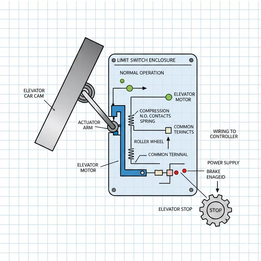
An elevator limit switch works by converting physical movement into an electrical signal that alters the behavior of the elevator control system when a predefined position is reached. The switch is mechanically actuated by a moving component of the elevator, such as the car, counterweight, or a cam mounted along the guide rail.
When the moving component contacts the actuator—typically a roller, lever, or plunger—the internal contacts of the limit switch change state. This change either opens or closes an electrical circuit, triggering a response such as stopping the motor, reducing speed, or engaging a safety interlock.
Elevator Car Movement
        |
        v
[ Cam / Vane ]
        |
        v
[ Limit Switch Actuator ]
        |
        v
[ Electrical Contact Change ]
        |
        v
[ Control or Safety Circuit Response ]
Elevator systems often use more than one type of limit switch to provide layered protection. The most common distinction is between normal limit switches and final limit switches.
| Feature | Normal Limit Switch | Final Limit Switch |
|---|---|---|
| Primary Purpose | Control stopping position | Emergency overtravel protection |
| Activation Frequency | Regular operation | Only during abnormal conditions |
| Circuit Type | Control circuit | Safety circuit |
| Reset Requirement | Automatic | Often manual inspection required |
Final limit switches are designed to activate only if normal stopping mechanisms fail. Once triggered, they typically prevent the elevator from returning to service until the underlying issue has been identified and corrected.
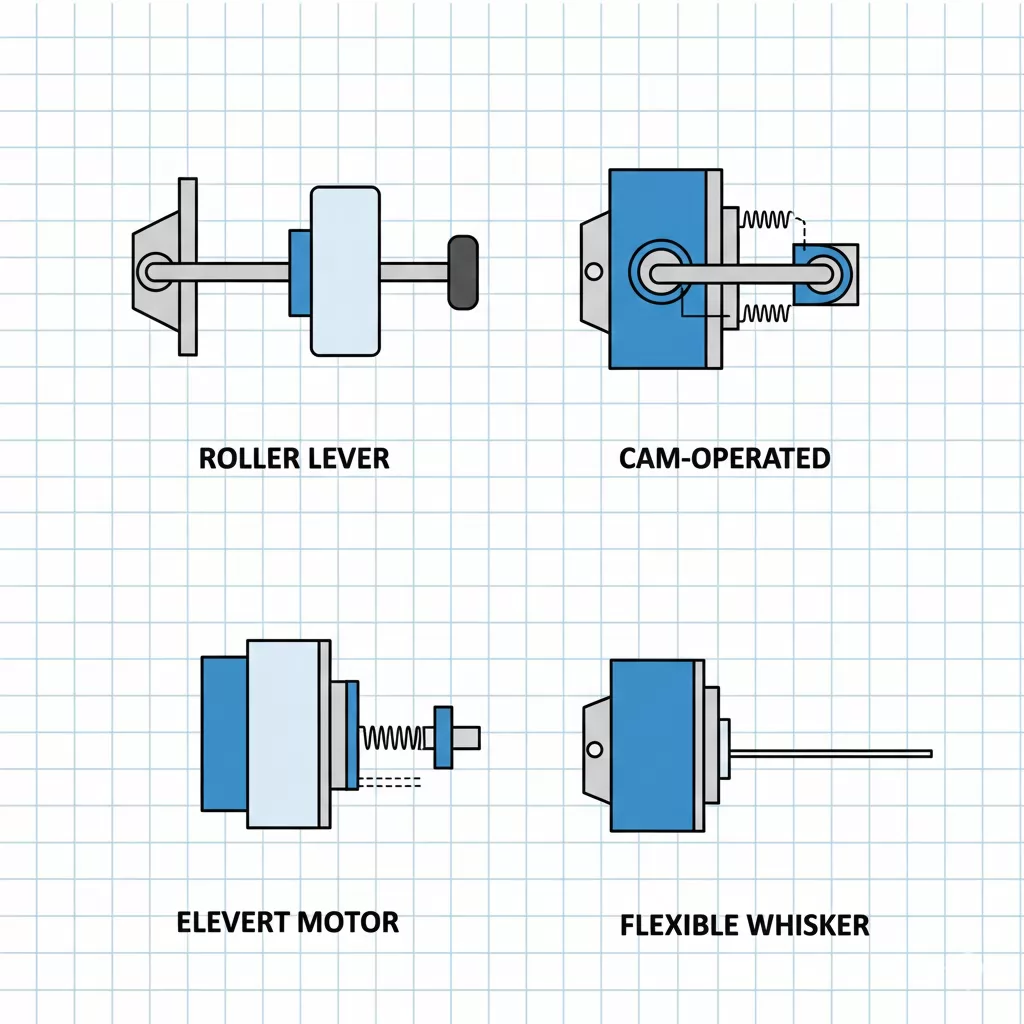
Elevator limit switches can be classified in several ways depending on their mechanical design, method of actuation, and application within the elevator system. Understanding these types helps engineers, maintenance teams, and procurement professionals select the correct switch for both safety and operational reliability.
The actuator determines how the limit switch physically responds when contacted by a moving component.
From a functional perspective, limit switches are installed to monitor specific elevator movements or safety conditions.
Limit switches may also differ in how their electrical contacts behave when actuated.
| Contact Type | Description | Typical Use Case |
|---|---|---|
| Normally Open (NO) | Circuit closes when actuated | Position confirmation signals |
| Normally Closed (NC) | Circuit opens when actuated | Safety circuits and fail-safe logic |
| Changeover (SPDT) | Switches between NO and NC | Flexible control and monitoring |
In safety-critical applications, normally closed contacts are often preferred because they allow the control system to detect wiring faults or switch failures through an open circuit condition.
Limit switches and safety switches are often mentioned together in elevator systems, but they serve different purposes and operate under different design philosophies. While both contribute to safe operation, understanding their distinctions is essential for proper system design, maintenance, and compliance.
A limit switch primarily monitors position or movement and signals the control system when a predefined limit is reached. A safety switch, on the other hand, is designed to interrupt power or motion immediately when a hazardous condition is detected, regardless of normal operating logic.
| Aspect | Limit Switch | Safety Switch |
|---|---|---|
| Primary Function | Position detection and control | Immediate hazard prevention |
| Typical Circuit | Control or monitoring circuit | Dedicated safety circuit |
| Activation Frequency | Regular or conditional operation | Only during abnormal or unsafe conditions |
| Reset Method | Usually automatic | Often requires manual inspection or reset |
| Examples | Terminal limit, slow-down switch | Door interlock, emergency stop switch |
Final limit switches occupy a unique position between standard limit switches and safety switches. Although they are mechanically similar to limit switches, they are typically wired into the safety circuit and only activate during extreme overtravel conditions.
For this reason, final limit switches are often treated as safety devices under elevator codes, even though their operating principle remains position-based rather than condition-based.
In practice, a well-designed elevator system uses both limit switches and safety switches together, creating layered protection that addresses both predictable operational limits and unexpected hazardous events.
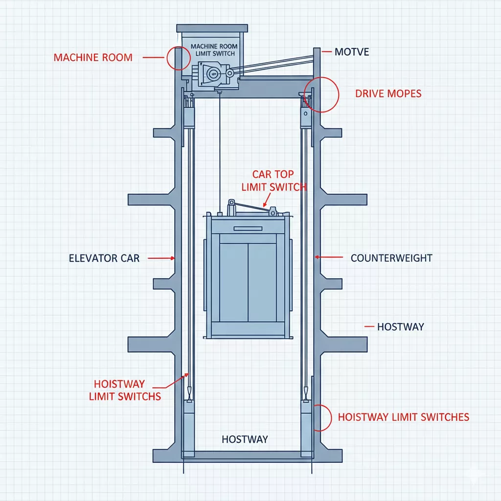
Elevator limit switches are installed at carefully selected locations to monitor critical movements and enforce safe travel boundaries. Their placement is determined by elevator type, hoistway design, and applicable safety standards. Correct installation ensures timely actuation and reliable protection under both normal and abnormal operating conditions.
The most common location for elevator limit switches is within the hoistway. These switches are typically mounted on the guide rails or hoistway walls and actuated by cams or vanes attached to the elevator car or counterweight.
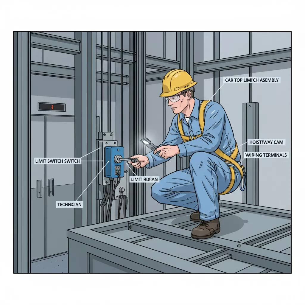
Some limit switches are mounted directly on the elevator car or car top, where they interact with fixed hoistway components. These installations are often used for position verification or maintenance-related safety functions.
In elevators with a dedicated machine room, certain limit switches may be integrated near drive equipment or control assemblies. These switches monitor mechanical positions related to motor operation or braking systems.
| Installation Location | Typical Switch Type | Primary Function |
|---|---|---|
| Hoistway (Upper/Lower) | Terminal / Final Limit Switch | Prevent overtravel |
| Guide Rail Mounted | Roller Lever Switch | Position detection |
| Car Top | Inspection Limit Switch | Maintenance safety |
| Door Zone Area | Position Confirmation Switch | Enable safe door operation |
Proper alignment between the actuator and the moving cam is critical. Misalignment, excessive vibration, or loose mounting hardware can delay or prevent switch actuation, increasing the risk of unsafe travel conditions.
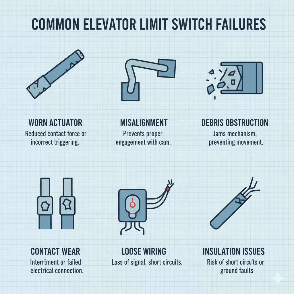
Although elevator limit switches are designed for durability and reliability, they are subject to mechanical wear, environmental exposure, and electrical degradation over time. Understanding common failure modes helps maintenance personnel diagnose issues quickly and reduce elevator downtime.
| Observed Symptom | Possible Cause | Recommended Action |
|---|---|---|
| Elevator stops unexpectedly | Misaligned or prematurely triggered switch | Inspect mounting and cam alignment |
| Failure to stop at terminal floor | Worn actuator or failed contacts | Test switch continuity and replace if needed |
| Intermittent faults | Loose wiring or vibration | Secure terminals and check cable routing |
| Inspection mode unavailable | Car top limit switch malfunction | Verify switch operation and safety circuit status |
Any failure involving safety or final limit switches should be treated as a critical issue. Elevators should not be returned to normal service until the cause has been identified, corrected, and verified through functional testing.
Regular maintenance and inspection of elevator limit switches are essential to ensure reliable operation and continued compliance with safety requirements. Because limit switches often serve as a final safeguard against overtravel or abnormal movement, their condition must be verified as part of routine elevator servicing.
During scheduled maintenance, technicians typically inspect limit switches for both mechanical integrity and electrical performance.
Functional testing confirms that the limit switch responds correctly under simulated operating conditions. This typically involves manually actuating the switch or slowly moving the elevator under inspection mode to observe system response.
| Inspection Interval | Typical Scope |
|---|---|
| Routine service visits | Visual inspection and basic functional check |
| Periodic safety inspections | Detailed testing and documentation |
| After abnormal events | Immediate inspection and corrective action |
Any adjustment, replacement, or rewiring of limit switches should be performed by qualified personnel. Improper installation or testing may compromise the safety circuit and violate local elevator codes.
Elevator limit switches must comply with a variety of international and regional safety standards. Adherence to these standards ensures both the safety of passengers and the reliability of the elevator system.
Understanding these standards is critical for elevator designers, installers, and maintenance personnel to ensure that limit switches perform as intended and meet legal requirements.
Selecting the correct elevator limit switch is essential to ensure reliable operation, compliance with safety standards, and long-term durability. Engineers and procurement teams should consider mechanical, electrical, and environmental factors when making a choice.
| Feature | Roller Lever | Plunger | Cam-Operated | Flexible / Whisker |
|---|---|---|---|---|
| Space Requirement | Moderate | Small | Moderate | Minimal |
| Mechanical Durability | High | Medium | High | Medium |
| Alignment Sensitivity | Moderate | High | Low | Low |
| Typical Application | Overtravel, position detection | Door zones, precise stops | Drive or shaft mechanisms | Confined or variable environments |
Choosing the right limit switch involves balancing operational requirements, space constraints, and safety obligations. Consulting the manufacturer’s specifications and verifying compliance with local standards are crucial steps in the selection process.
The primary purpose is to detect the position of the elevator car or counterweight and trigger a control or safety response when predefined travel limits are reached, preventing overtravel and mechanical damage.
Routine inspections are recommended during regular service visits, typically every 6–12 months depending on usage. Final limit and safety-related switches should be tested during periodic safety inspections or after any abnormal event.
Yes. Mechanical wear, misalignment, or electrical contact issues can prevent proper actuation. Therefore, periodic functional testing is essential to ensure reliable operation.
Normal limit switches control stopping points under regular operation, while final limit switches are designed to activate only during overtravel or abnormal conditions, often wired into safety circuits.
Yes. Limit switches must comply with international and regional standards such as ISO 22559, IEC 60947-5-1, ASME A17.1 / CSA B44, EN 81, and GB 7588, depending on the location of installation and regulatory requirements.
Consider actuator type, contact configuration, electrical rating, environmental conditions, code compliance, and redundancy requirements. Consulting manufacturer specifications and verifying adherence to local safety standards is essential.
Any failure involving a safety or final limit switch should be treated as critical. The elevator must be taken out of service until the switch is inspected, tested, and replaced if necessary by qualified personnel.


.png)