










_1794967688_WNo_1600d900.webp)
Traction elevator components work together to move an elevator car smoothly and safely between floors. A typical traction elevator uses a motor-driven traction machine, traction sheave, suspension ropes or belts, counterweight, guide rails, guide shoes, and a range of supporting and safety devices. Each part has a specific role in transmitting driving force, balancing the load, guiding the car, and controlling vertical movement.
Understanding traction elevator components is important when planning a new installation, upgrading an existing elevator, or purchasing replacement parts. The correct selection depends on more than a component's name or appearance. Rated load, operating speed, suspension ratio, sheave diameter, rope specifications, rail profile, and equipment compatibility all influence whether a part is suitable for a particular elevator. This guide explains the main traction elevator parts, their functions, how they work together, and what buyers should check before ordering.
- What Are Traction Elevator Components?
- What Are the Main Components of a Traction Elevator?
- Traction Elevator Machine: Geared vs. Gearless
- Traction Sheaves and Deflector Sheaves
- Elevator Suspension Ropes and Belts
- Counterweight and Compensation System
- Elevator Guide Rails, Fishplates, and Guide Shoes
- Traction Machine Brake and Safety Components
- Traction Elevator Control and Positioning Components
- How Do Traction Elevator Components Work Together?
- How to Select the Right Traction Elevator Components
- Traction Elevator Component Replacement and Maintenance
- FAQs About Traction Elevator Components
- Conclusion
1. What Are Traction Elevator Components?
A traction elevator is an electric elevator that uses friction between a traction sheave and suspension ropes or belts to move the car. The suspension arrangement usually connects the elevator car and counterweight, allowing them to travel in opposite directions. The traction machine supplies the driving force, while the controller coordinates movement, stopping, and other operating functions.
Unlike a hydraulic elevator, which uses pressurized fluid and a cylinder to lift the car, a traction elevator relies on a motor-driven suspension system. This arrangement is widely used in residential, commercial, office, hotel, and high-rise buildings. Depending on the project, traction elevators may use geared or gearless machines, different suspension ratios, and machine-room or machine-room-less configurations.
Traction elevator components can be divided into several functional groups:
| Component Group | Main Parts | Primary Function |
|---|---|---|
| Drive system | Traction machine, motor, gearbox, traction sheave | Generates and transfers the force required to move the elevator. |
| Suspension system | Steel wire ropes or belts, rope terminations, suspension accessories | Supports and connects the car and counterweight. |
| Balancing system | Counterweight frame, counterweight blocks, compensation chain | Balances the car and helps manage changing suspension weight. |
| Guiding system | Guide rails, fishplates, brackets, guide shoes | Maintains the alignment and travel path of the car and counterweight. |
| Braking and safety system | Machine brake, overspeed governor, safety gear, buffers | Supports controlled stopping and protection under specified abnormal conditions. |
| Control and feedback system | Controller, variable frequency drive, encoder, position sensors | Coordinates elevator movement and monitors operating conditions. |
| Supporting equipment | Deflector sheaves, traveling cables, brackets, fasteners | Supports rope routing, electrical connections, and installation stability. |
These groups are closely connected. For example, the traction machine cannot be selected independently of the suspension arrangement, rope specifications, counterweight, and control system. A change in one component may affect the requirements of other parts.
2. What Are the Main Components of a Traction Elevator?
The exact configuration of a traction elevator depends on its rated load, speed, building height, suspension ratio, and installation layout. However, most conventional traction systems share several major components.
2.1 Traction Machine
The traction machine is the main driving unit of a traction elevator. It converts electrical energy into rotational mechanical power and transfers that power to the traction sheave. Depending on the design, the machine may be geared or gearless.
2.2 Traction Sheave
The traction sheave is the grooved wheel that contacts the suspension ropes or belts. Its rotation creates the traction force needed to move the elevator car and counterweight. Sheave diameter, groove profile, material, and rope compatibility are important selection factors.
2.3 Suspension Ropes or Belts
Suspension ropes or belts connect the elevator car and counterweight through the traction arrangement. They support the suspended assemblies and transmit the forces required for movement. Their construction and specifications must match the elevator's design.
2.4 Counterweight
The counterweight balances the elevator car and part of its rated load. It reduces the difference in force that the traction machine must overcome, helping the drive system operate efficiently.
2.5 Guide Rails
Guide rails provide the vertical guiding path for the elevator car and counterweight. They are fixed to the shaft structure using brackets and connected in sections with suitable rail joints or fishplates.
2.6 Guide Shoes or Roller Guides
Guide shoes and roller guides connect the moving assemblies to the guide rails. They help maintain alignment and limit unwanted lateral movement while the elevator travels.
2.7 Compensation Chain
A compensation chain or other approved compensation arrangement may be used to offset changes in the effective weight of the suspension ropes as the elevator car moves through the shaft. This becomes particularly important in installations with greater travel heights.
2.8 Controller and Position Feedback Devices
The controller coordinates the elevator's operating sequence, while encoders and position sensors provide information about motor or car movement. These devices work with the drive system to support acceleration, deceleration, stopping, and floor leveling.
The main components must be selected as a coordinated set. A traction machine with the correct nominal load rating may still be unsuitable if its sheave, suspension ratio, mounting arrangement, or control requirements do not match the existing installation.
3. Traction Elevator Machine: Geared vs. Gearless
The traction machine supplies the mechanical power needed to move the elevator car. One of the first decisions when selecting a traction machine is whether the installation requires a geared or gearless design. These two machine types use different transmission arrangements and should not be treated as interchangeable replacement options.
3.1 Geared Traction Machine
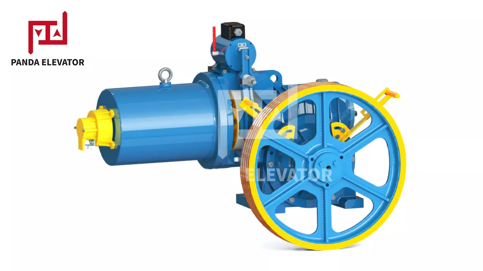
A geared traction machine uses a gearbox between the motor and traction sheave. The gearbox reduces motor speed and transfers torque to the sheave. This arrangement has been widely used in conventional elevator installations and may be suitable for certain low- and medium-speed applications.
Geared machines can be considered when replacing an existing geared unit, especially if the machine room, supporting beams, and surrounding equipment were designed around that configuration. Buyers should check the gearbox arrangement, machine dimensions, rated load, speed, sheave, and mounting details.
3.2 Gearless Traction Machine
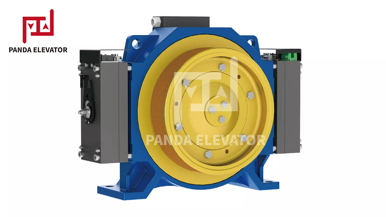
A gearless traction machine drives the traction sheave without a conventional reduction gearbox. Many modern gearless machines use permanent magnet synchronous motors and are designed for compact installation, efficient operation, and controlled elevator movement.
Gearless machines are commonly considered for new installations and modernization projects where the building layout and control equipment support the required configuration. They may be used in machine-room-less elevators as well as other traction elevator arrangements.
3.3 Geared vs. Gearless Traction Machines
| Comparison Factor | Geared Machine | Gearless Machine |
|---|---|---|
| Transmission | Uses a gearbox between the motor and sheave. | Drives the sheave without a conventional reduction gearbox. |
| Typical design considerations | Existing machine-room layout and gearbox arrangement. | Motor torque, sheave configuration, and controller compatibility. |
| Maintenance | May require gearbox-related inspection and lubrication. | Requires inspection of the motor, brake, bearings, and associated equipment. |
| Modernization | May be practical when replacing an existing geared machine. | May require changes to the supporting structure, control system, or installation layout. |
| Selection priorities | Load, speed, gearbox ratio, machine weight, and mounting dimensions. | Load, speed, torque, sheave, suspension ratio, and electrical compatibility. |
Panda lists both geared and gearless traction machine options in its elevator traction system category. Its listed product range includes gearless models such as MONA200 and MCK100, as well as geared models such as YJ150, YJ125, and YJ110A. Buyers should confirm the current model specifications and suitability for their elevator before ordering.
3.4 Important Traction Machine Specifications
When comparing traction machines, check the following information rather than relying on the model name alone:
- Rated load: Confirm the machine's specified duty and the elevator's car and rated-load information.
- Rated speed: Check the machine's permitted speed range against the elevator's design speed.
- Suspension ratio: Verify whether the installation uses 1:1, 2:1, or another approved arrangement.
- Sheave diameter: Match the sheave dimensions and groove profile to the suspension system.
- Voltage and electrical requirements: Check the supply voltage, motor parameters, and drive compatibility.
- Machine weight and dimensions: Confirm the supporting structure, lifting route, and available installation space.
4. Traction Sheaves and Deflector Sheaves
Sheaves are important mechanical parts in a traction elevator's rope arrangement. The traction sheave transfers driving force from the machine to the suspension ropes, while deflector or diversion sheaves guide the ropes along the required path. Their dimensions and groove geometry affect rope contact, traction, and system compatibility.
4.1 Traction Sheave
The traction sheave is mounted on the traction machine and contains grooves designed for the specified suspension ropes or belts. As the machine rotates the sheave, friction between the groove surfaces and suspension members enables the car and counterweight to move.
Sheave diameter is an important parameter, but it is not the only one. Rope diameter, groove profile, groove depth, material, and the machine's design all need to be considered. A sheave with the correct outside diameter may still be unsuitable if its grooves do not match the rope.
4.2 Deflector Sheave
A deflector sheave changes the direction of the suspension ropes to achieve the required routing within the elevator system. Its location and dimensions depend on the machine position, suspension ratio, car arrangement, and available shaft or machine-room space.
4.3 Cast Iron and Nylon Sheaves
Cast iron and nylon are two materials used in certain elevator sheave applications. Cast iron sheaves are commonly used in traction-related equipment, while nylon sheaves may be selected for specific applications where weight and operating noise are considerations. The appropriate material depends on the machine design and the rope arrangement.
Panda lists cast iron and nylon elevator sheave options in its traction system product range. Buyers should confirm the actual application, material, groove profile, rope specification, and available dimensions for the selected model.
4.4 How to Select an Elevator Sheave
| Selection Parameter | What to Check | Why It Matters |
|---|---|---|
| Sheave diameter | Original machine specification and installation dimensions. | Must match the designed traction arrangement. |
| Rope diameter | Actual suspension rope diameter and specification. | Determines the required groove dimensions. |
| Groove profile | Groove shape, depth, and contact geometry. | Affects rope contact and traction behavior. |
| Material | Cast iron, nylon, or another specified material. | Must suit the machine and operating conditions. |
| Mounting arrangement | Shaft, bearing, and machine connection details. | Ensures correct installation and alignment. |
5. Elevator Suspension Ropes and Belts
Suspension ropes or belts support the elevator car and counterweight and transmit the forces required for vertical movement. They are critical load-bearing parts of a traction elevator and must meet the design requirements of the machine and suspension arrangement.
5.1 Steel Wire Ropes
Steel wire ropes are widely used in conventional traction elevators. They are made from multiple steel wires arranged into strands and laid around a core. Their construction, diameter, tensile properties, and other characteristics determine their suitability for a specific elevator.
Rope selection should consider rated load, suspension ratio, traction sheave diameter, rope groove profile, travel height, and the elevator manufacturer's specifications. The number of ropes and their arrangement must also match the original engineering design.
5.2 Elevator Suspension Belts
Some modern traction elevators use coated steel belts or other engineered suspension belts instead of conventional round wire ropes. These products have their own dimensional, bending, and compatibility requirements. A belt-based system must use the traction machine and sheave arrangement designed for that suspension medium.
5.3 Suspension Ratio: 1:1 and 2:1
The suspension ratio describes the relationship between rope movement and elevator car movement. In a 1:1 arrangement, the car moves approximately the same distance as the rope movement. In a 2:1 arrangement, the rope passes through a moving sheave arrangement so that the car moves approximately half the rope travel.
This difference affects rope routing, sheave loading, machine speed requirements, and the overall elevator configuration. A machine designed for one suspension ratio should not be assumed to work correctly with another ratio.
5.4 Rope and Sheave Compatibility
The rope and traction sheave must be treated as a matched combination. Important checks include:
- Rope diameter and construction.
- Sheave diameter and groove profile.
- Rope material and applicable technical requirements.
- Suspension ratio and rope routing.
- Rated load, speed, and traction requirements.
- Manufacturer limits for wear, inspection, and replacement.
Rope replacement should never be based only on an approximate diameter. Qualified elevator personnel should verify the original specifications, installation arrangement, and applicable replacement criteria.
6. Counterweight and Compensation System
The counterweight is a major part of the traction elevator's balancing arrangement. It helps balance the weight of the car and a portion of its rated load, reducing the net force that the traction machine needs to overcome during operation.
6.1 Counterweight Frame
The counterweight frame holds the counterweight blocks and connects the assembly to the suspension arrangement. Its dimensions, structural design, and connection points must match the elevator's engineering specifications.
6.2 Counterweight Blocks
Counterweight blocks provide the mass required by the elevator's balancing calculation. Their quantity and total weight are determined by the car mass, rated load, and system design. The counterweight must not be adjusted arbitrarily because its mass directly affects traction and drive requirements.
6.3 Compensation Chain
A compensation chain helps balance changes in the effective weight of the suspension ropes as the elevator car moves. In taller installations, the length of rope hanging on each side of the traction system changes significantly with car position. The compensation arrangement helps manage this changing weight distribution.
Compensation chains may use protective wrapping or a full plastic construction, depending on the product design. Selection factors can include weight per metre, total length, bending diameter, breaking load, and the elevator's travel height.
6.4 Why Compensation Chain Selection Matters
The compensation chain is not simply an optional accessory for every traction elevator. Its use and specifications depend on the elevator design. An unsuitable compensation weight may affect the balance of the suspension system and the load experienced by the drive equipment.
Panda lists elevator compensation chains as part of its traction elevator product range. Buyers should provide the travel height, existing rope arrangement, required chain length, and relevant technical information when asking for a suitable product.
| Component | Function | Important Selection Factors |
|---|---|---|
| Counterweight frame | Holds and supports the counterweight blocks. | Frame dimensions, connection points, structural design. |
| Counterweight blocks | Provide the required balancing mass. | Total weight, block dimensions, and elevator design. |
| Compensation chain | Helps offset changes in suspension rope weight. | Weight per metre, length, bending diameter, and travel height. |
| Rope terminations | Connect suspension ropes to designated assemblies. | Rope type, connection design, and approved installation details. |
7. Elevator Guide Rails, Fishplates, and Guide Shoes
The guiding system keeps the elevator car and counterweight aligned as they move through the hoistway. It consists mainly of guide rails, rail brackets, fishplates, fasteners, and guide shoes or roller guides. Proper selection and installation are important for stable movement and the correct operation of the elevator.
7.1 Elevator Guide Rails
Guide rails are vertically installed structural components that provide a guiding surface for the elevator car and counterweight. They are commonly supplied in standardized rail profiles and lengths, with machining and dimensional requirements depending on the elevator design.
Important guide rail specifications include rail type, profile, dimensions, material, straightness, machining accuracy, and connection arrangement. The required rail must be compatible with the guide shoes, brackets, and elevator installation.
7.2 Guide Rail Fishplates
Guide rail fishplates connect adjacent guide rail sections and help maintain the alignment and stability of the rail assembly. They are designed for particular rail profiles and connection dimensions.
A fishplate should not be selected only by its overall length or appearance. Its hole positions, thickness, dimensions, and rail compatibility must match the guide rail system. An incorrect fishplate can make proper alignment and installation difficult.
7.3 Guide Rail Brackets
Guide rail brackets secure the rails to the hoistway structure. Their type and spacing depend on the building structure, rail arrangement, and elevator engineering requirements. The brackets must provide the required support under the specified operating conditions.
7.4 Guide Shoes and Roller Guides
Guide shoes or roller guides are installed on the elevator car frame and counterweight frame. They engage with the guide rails and help control lateral movement during travel.
Sliding guide shoes use a sliding contact surface, while roller guides use rollers to follow the rail. The appropriate type depends on the elevator design, operating speed, load, and manufacturer requirements.
7.5 Guide Rail System Selection Checklist
| Part | What to Confirm | Common Compatibility Concern |
|---|---|---|
| Guide rail | Rail profile, dimensions, material, and machining. | Must match the guide system and installation design. |
| Fishplate | Rail section, hole spacing, thickness, and dimensions. | Must fit the specific rail profile and joint arrangement. |
| Rail bracket | Bracket type, fixing method, and mounting dimensions. | Must suit the rail and hoistway structure. |
| Guide shoe | Rail interface, dimensions, and sliding or roller design. | Must match the car or counterweight guide arrangement. |
| Fasteners | Size, grade, and specified connection method. | Must meet the installation and structural requirements. |
Panda provides traction system products, including machined guide rails and elevator guide rail fishplates. Buyers can review the product category and confirm the required rail section and connection dimensions before requesting a quotation.
8. Traction Machine Brake and Safety Components
The braking and safety arrangements help control elevator movement and respond to specified abnormal conditions. The machine brake is part of the traction drive, while other safety devices perform separate protective functions. Their selection and maintenance must follow the elevator's approved design and applicable safety requirements.
8.1 Traction Machine Brake
The machine brake is generally designed to hold the traction machine stationary when the elevator is not moving and to provide the required braking action during operation. Its construction and monitoring arrangement depend on the traction machine model.
When replacing or servicing a brake assembly, check the machine model, brake type, electrical requirements, mechanical dimensions, and manufacturer specifications. Brake components should not be modified or substituted without professional approval.
8.2 Overspeed Governor
The overspeed governor monitors elevator speed. If the elevator exceeds its specified triggering threshold, the governor activates the associated protective arrangement according to the elevator design.
8.3 Safety Gear
Safety gear is a mechanical safety device designed to engage with the guide rails under specified abnormal conditions. It is commonly connected to the overspeed protection arrangement and must be matched to the elevator's rated parameters and approved configuration.
8.4 Elevator Buffers
Buffers are installed at designated locations in the elevator shaft to absorb energy if the car or counterweight reaches the end of its permitted travel under specified conditions. Different buffer designs are used according to the elevator's speed, load, and installation requirements.
8.5 Limit Switches and Safety Circuits
Limit switches and other safety circuit devices provide signals or protective actions at designated operating positions. They work with the controller and other safety equipment to help prevent operation outside the approved travel limits.
When purchasing safety components, confirm the exact model, rated parameters, installation dimensions, and approved application. A component that looks similar to the original may not have the same safety performance or compatibility.
For related products, buyers can also review Panda's elevator safety components category.
9. Traction Elevator Control and Positioning Components
The control system coordinates the operation of the traction machine and other elevator equipment. It processes passenger requests, receives feedback from sensors, and controls the drive system to achieve the required movement and stopping sequence.
9.1 Elevator Controller
The elevator controller acts as the main control unit. It processes signals from operating panels, position sensors, door circuits, and other devices. It then coordinates the drive and related equipment according to the elevator's control logic.
9.2 Variable Frequency Drive
A variable frequency drive (VFD) controls the speed of the traction motor by adjusting the electrical frequency and voltage supplied to it. In a traction elevator, the drive works with the controller to manage acceleration, deceleration, and stopping performance.
9.3 Encoder
An encoder provides feedback about motor rotation or position. The controller uses this information to monitor movement and coordinate the drive system. Encoder type, resolution, electrical interface, and mounting arrangement must be compatible with the motor and controller.
9.4 Position and Leveling Sensors
Position and leveling sensors provide information about the car's location in the hoistway. They help the control system determine when to decelerate, stop, and level the car with a landing. Their installation and signal requirements depend on the elevator configuration.
9.5 Control Wiring and Communication Devices
Control wiring connects the controller, drive, motor, sensors, door equipment, and other electrical components. Communication devices may also be used to exchange operating information between different parts of the elevator system.
When replacing control components, buyers should check the controller model, drive type, motor parameters, encoder interface, wiring arrangement, and communication requirements. A component with a similar appearance may use a different signal or connection configuration.
Panda offers related products through its elevator control system category. For a broader review of available elevator parts, buyers can also visit the elevator parts catalog.
10. How Do Traction Elevator Components Work Together?
Traction elevator components operate as a coordinated system. The controller receives a passenger request, checks the relevant operating conditions, and coordinates the traction machine, brake, and other equipment to move the car to the selected floor.
- Passenger request: A passenger presses a landing call button or selects a destination using the car operating panel.
- Signal processing: The elevator controller receives the request and determines the required operating response.
- Safety condition check: The control system checks relevant signals, including door-lock status and other required safety conditions.
- Brake release and drive activation: When the required conditions are satisfied, the controller coordinates the brake and traction drive according to the elevator's operating sequence.
- Traction force transmission: The motor rotates the traction sheave, and friction between the sheave grooves and suspension ropes or belts moves the elevator car and counterweight.
- Guided vertical movement: Guide shoes or roller guides follow the guide rails to maintain the required alignment of the moving assemblies.
- Position monitoring: Encoders and position sensors provide feedback to the controller as the elevator approaches the destination floor.
- Deceleration and leveling: The controller coordinates the drive to slow the car and bring it to the designated landing position.
- Stopping and passenger access: The drive and brake complete the stopping sequence, and the door system opens when the required conditions are met.
Throughout this process, the counterweight helps balance the car, while the compensation arrangement manages changes in suspension weight where required. Safety devices monitor specific conditions and provide protective functions as designed.
11. How to Select the Right Traction Elevator Components
Selecting traction elevator components requires accurate technical information about the existing elevator or new installation. Buyers should identify the system configuration first, then compare the required component specifications with the manufacturer's product data.
11.1 Confirm the Elevator Configuration
Identify whether the elevator uses a geared or gearless traction machine, its suspension ratio, machine-room arrangement, and overall system design. These details determine which machine and supporting components are applicable.
11.2 Check Rated Load and Speed
Rated load and speed are fundamental parameters for traction machine selection. Use the elevator's nameplate, technical drawings, and original documentation to confirm the required values. Do not estimate machine duty from passenger capacity alone.
11.3 Verify the Suspension Ratio
Confirm whether the elevator uses a 1:1, 2:1, or another specified suspension arrangement. The ratio affects rope routing, sheave configuration, machine requirements, and car movement.
11.4 Match the Sheave and Suspension Ropes
When replacing a traction sheave or suspension rope, check both components together. Confirm rope diameter, rope construction, groove profile, sheave diameter, and other relevant technical details.
11.5 Confirm Guide Rail and Fishplate Dimensions
For guide rail components, provide the rail profile, dimensions, connection details, and required length. Fishplates must match the specific rail section and hole arrangement.
11.6 Check Counterweight and Compensation Requirements
Confirm the counterweight arrangement and whether the elevator uses a compensation chain. For compensation products, provide the travel height, required length, weight per metre, bending diameter, and other relevant design information.
11.7 Review Electrical and Mechanical Compatibility
For traction machines and control components, verify electrical ratings, motor type, encoder interface, brake configuration, mounting dimensions, and controller compatibility. Mechanical and electrical compatibility should be checked together.
11.8 Request Technical Documentation
Ask the supplier for relevant product specifications, dimensional drawings, installation details, and applicable quality or conformity documentation. For safety-related components, verify the requirements that apply to the specific elevator and market.
| Component | Key Information to Provide | Selection Purpose |
|---|---|---|
| Traction machine | Rated load, speed, suspension ratio, voltage, weight, dimensions. | Confirms machine duty and installation compatibility. |
| Traction sheave | Diameter, rope diameter, groove profile, material, mounting details. | Ensures the sheave matches the suspension system. |
| Suspension rope | Diameter, construction, quantity, rated specifications, suspension ratio. | Confirms suitability for the elevator's suspension design. |
| Guide rail | Rail profile, dimensions, material, machining, length. | Ensures correct fit and guiding arrangement. |
| Fishplate | Rail type, hole spacing, plate dimensions, thickness. | Ensures compatibility between adjacent rail sections. |
| Compensation chain | Travel height, length, weight per metre, bending diameter. | Matches the compensation arrangement to the elevator design. |
| Controller and encoder | Model, motor type, voltage, signal interface, wiring details. | Supports correct electrical and control integration. |
Preparing a component specification sheet before contacting suppliers can reduce repeated technical questions and help avoid ordering errors. Include the original part number, equipment nameplate, dimensions, photos, drawings, and operating parameters whenever possible.
12. Traction Elevator Component Replacement and Maintenance
Regular inspection and maintenance help identify wear, damage, and abnormal operating conditions in a traction elevator. Maintenance procedures and inspection intervals should follow the elevator manufacturer's documentation, applicable regulations, and the requirements of the specific installation.
12.1 Inspect the Traction Machine
Qualified maintenance personnel should inspect the machine, motor, brake, bearings, and other specified parts. Unusual noise, vibration, temperature, or changes in operating behavior should be investigated using approved procedures.
12.2 Check the Traction Sheave and Suspension Ropes
The traction sheave and suspension ropes should be inspected according to the manufacturer's criteria. Check for relevant signs of wear, damage, abnormal contact, or other conditions that may affect the traction arrangement. Replacement decisions must be based on technical requirements rather than appearance alone.
12.3 Monitor Guide Rails and Guide Shoes
Guide rails, fishplates, brackets, and guide shoes should be checked for alignment, fastening condition, wear, and damage. Abnormal vibration or noise may indicate a problem in the guiding system or another connected assembly.
12.4 Inspect the Counterweight and Compensation Arrangement
The counterweight frame, blocks, connections, and compensation chain should be inspected according to the elevator design. Any changes to counterweight mass or compensation components require professional evaluation.
12.5 Check the Brake and Safety Devices
The machine brake, overspeed governor, safety gear, buffers, and other protective devices require inspection and testing in accordance with the applicable maintenance procedures. These components should not be adjusted or replaced by unqualified personnel.
12.6 Keep Accurate Replacement Records
Record the model numbers, part numbers, installation dates, inspection results, and replacement history of important components. These records help maintenance teams identify the correct spare parts and manage future procurement.
When a replacement is necessary, use the original technical documentation and confirm the new component's specifications with the equipment manufacturer or a qualified elevator professional. This is especially important for traction machines, suspension ropes, sheaves, and safety-related products.
13. FAQs About Traction Elevator Components
13.1 What are the main components of a traction elevator?
The main components typically include a traction machine, traction sheave, suspension ropes or belts, counterweight, guide rails, guide shoes, controller, brake, and relevant safety devices. Some installations also use deflector sheaves and compensation chains.
13.2 What is the most important component in a traction elevator?
No single component can ensure the operation of the entire elevator. The traction machine provides driving force, the suspension system transfers that force, the counterweight helps balance the car, and the controller coordinates movement. Reliable operation depends on the correct design and interaction of all components.
13.3 What is the difference between geared and gearless traction machines?
A geared traction machine uses a gearbox between the motor and traction sheave. A gearless machine drives the sheave without a conventional reduction gearbox. The appropriate type depends on the elevator's load, speed, installation arrangement, control system, and modernization requirements.
13.4 What does a traction sheave do?
The traction sheave is a grooved wheel driven by the traction machine. It transfers rotational power to the suspension ropes or belts through friction, allowing the elevator car and counterweight to move.
13.5 What is the difference between 1:1 and 2:1 elevator suspension?
In a 1:1 arrangement, the car moves approximately the same distance as the rope movement. In a 2:1 arrangement, the rope passes through a moving sheave arrangement, so the car moves approximately half the rope travel. The suspension ratio affects rope routing, sheave arrangement, and machine selection.
13.6 Why must the traction sheave match the suspension rope?
The rope and sheave grooves are designed to work together. Incorrect rope diameter or groove geometry can affect rope contact and traction behavior. Buyers should confirm the rope specification and sheave groove profile together before ordering.
13.7 What is the function of an elevator compensation chain?
A compensation chain helps offset changes in the effective weight of the suspension ropes as the elevator car moves through the shaft. Its use and specifications depend on the elevator's travel height and engineering design.
13.8 What is the purpose of guide rail fishplates?
Guide rail fishplates connect adjacent sections of elevator guide rails. They help maintain the alignment and stability of the rail assembly. The fishplate must match the rail profile and connection dimensions.
13.9 Can I replace a geared traction machine with a gearless machine?
Not without checking the complete elevator configuration. The suspension ratio, machine dimensions, weight, supporting structure, sheave, controller, and electrical requirements may differ. A qualified elevator professional should evaluate the proposed replacement before any change is made.
13.10 How do I choose the right traction elevator spare parts?
Start with the elevator model, original part number, rated load, speed, suspension ratio, and component dimensions. For sheaves and ropes, confirm their specifications as a matched set. For guide rails and fishplates, verify the rail profile and connection details. Ask the supplier for technical documentation when necessary.
13.11 Where can I buy traction elevator components?
Traction elevator components can be sourced from elevator manufacturers, authorized distributors, and specialized elevator spare-parts suppliers. Before ordering, confirm product specifications, equipment compatibility, documentation, lead time, and technical support.
14. Conclusion
Traction elevator components form an interconnected mechanical and electrical system that enables an elevator to move safely and efficiently. The traction machine and sheave generate and transfer driving force, suspension ropes or belts support the car, the counterweight helps balance the system, and guide rails maintain the required travel path. The controller, brake, sensors, and safety devices coordinate and protect the operation.
For elevator contractors, maintenance companies, and equipment buyers, understanding the function and compatibility of each component is essential when selecting or replacing traction elevator parts. Before purchasing, verify the rated load, speed, suspension ratio, sheave and rope specifications, guide rail dimensions, and relevant electrical or mechanical interfaces. Accurate technical information helps reduce ordering errors and supports reliable equipment performance.
Panda provides a range of elevator products, including traction machines, elevator sheaves, guide rails, guide rail fishplates, and compensation chains. Visit Panda Elevator Parts to explore its product range, or review the elevator traction system category for more information about available traction-related products.
If you are sourcing replacement components, prepare the existing equipment nameplate, component model, dimensions, and relevant installation details before contacting the supplier. Panda can be contacted to discuss product information and quotation requirements.